
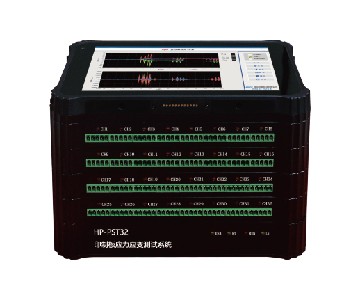
The HP-PST Series is a multi-channel PCB strain/stress testing system designed for strain-gage measurements during PCB assembly, test, and reliability validation. It supports synchronous sampling, real-time curves, OK/NG judgment, and one-click report generation/printing, with strong anti-interference design for On-site environment. (Industry strain-gage testing is commonly aligned to IPC/JEDEC guidance for PCB strain measurement.)
| Anti-interference performance | Power/ground isolation between acquisition boards reduces On-site interference. |
|---|---|
| True multi-point independence | Each measurement point can select input type, minimizing mutual interference (no reliance on relay/e-switch channel switching). |
| Automated decision & reporting | Built-in OK/NG judgment + report generation + print to speed up validation workflows. |
| Stable long-term measurement: | Independent DA balancing (per channel) without losing measurement range; independent AD measurement. |
| High-speed synchronous capture | All channels sample/display/save synchronously up to 20 kHz max sampling. |
| Modular scalability | Configure measurement points based on real test needs (building-block expansion). |
Multi-channel PCB strain measurement: 8 to 64 channels
Wide sampling range: 0.1 Hz to 20 kHz (1 Hz step setting in software)
High-resolution acquisition: 24-bit ADC, ±0.2% accuracy
Built-in workflow: parameter setup → live display → save → playback → analysis → report → print
Designed for noisy shop floors: inter-channel isolation + robust anti-interference capability
Standards-aligned visualization: supports strain and strain-rate observation per IPC/JEDEC-9704A-type requirements (and related industry practice)
HP-PST focuses on PCB strain gauge testing, helping teams quantify strain during processes like fixture clamping, screw fastening, depaneling, handling, or assembly steps that may damage solder joints or sensitive packages. It provides:
Condition setup + statistics + curve plotting
Automatic OK/NG judgment
One-click test report generation + one-click printing
Long-term data storage and export for third-party software use
(For context: IPC/JEDEC-9704 guidance is widely referenced for PCB strain gage test setups and evaluation.)
PCB assembly process validation (fixture design, clamping/pressing operations)
Board flex / strain risk evaluation near BGA or sensitive components
Depaneling, screw torque/fastening impact studies
Production-line troubleshooting for intermittent solder joint failures
R&D reliability and mechanical stress characterization of PCB designs
Strain measurement bridge types supported:
Full bridge
Half bridge
Quarter bridge (3-wire)
Quarter bridge (2-wire)
Quarter bridge (compensation bridge)
Bridge excitation: 3 V (0.1% accuracy)
Channel design highlights:
Inter-channel isolation to reduce cross-talk/interference
Input type selectable per measurement point
Digital + analog compensation methods available (keeps channels isolated and reduces compensation-induced coupling)
Measurement channels: 8–64
Sampling frequency: 0.1 Hz–20 kHz (software settable, 1 Hz step)
Sampling mode: Multi-channel synchronous sampling
ADC resolution: 24-bit
Measurement accuracy: ±0.2%
Strain range options: ±32768 με / ±50000 με / ±100000 με
Minimum resolution: 0.1 με
Anti-aliasing filter: Cutoff = sampling frequency / 2.56; stopband attenuation > -80 dB/Oct
Zero/balance: Full-range independent DA auto-zero (does not sacrifice measurement range)
Display: Built-in Windows 10; 8-inch 1280×800 capacitive touchscreen
Storage: 32 GB onboard (optional 32 GB TF card expansion)
Power: Built-in lithium battery; up to 8 hours operation
1) What is a PCB strain test used for?
It quantifies PCB deformation during assembly/test so you can detect steps that may overstress components or solder joints (a common motivation behind IPC/JEDEC-9704-type guidance).
2) How many channels can HP-PST measure?
From 8 to 64 channels, with synchronous sampling across all points.
3) What sampling speed do I need for PCB strain testing?
Slow operations may use low Hz sampling; dynamic events (pressing, depaneling, snapping) may require much higher rates—HP-PST supports up to 20 kHz.
4) Does it support common strain gauge wiring?
Yes—full/half/quarter bridge (2-wire/3-wire) and compensation bridge modes are supported.
5) Can it automatically generate reports?
Yes—condition setup, statistics, curves, OK/NG judgment, and one-click report + print are built in.
6) Can I export data to other software?
Yes—data can be saved in multiple formats for third-party software calls/integration.
7) Is IPC/JEDEC-9704 relevant here?
Yes—PCB strain gage testing commonly references IPC/JEDEC-9704 guidance, and many industry solutions position compliance around it.